FILE / 01
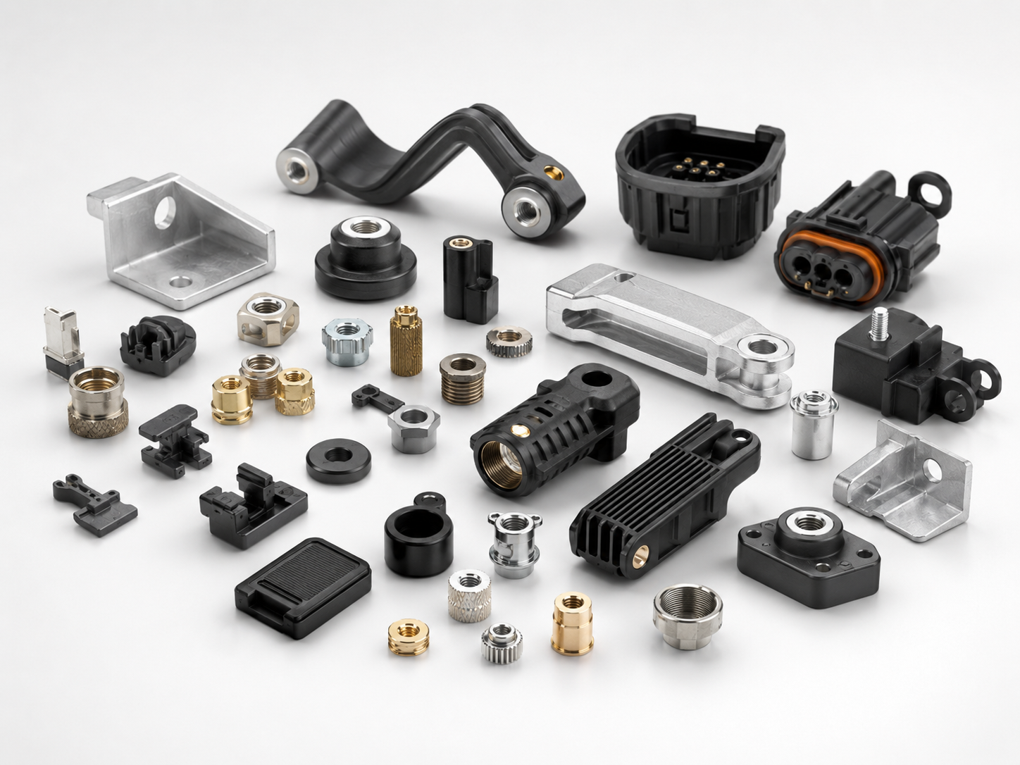
Machined Components
Evaluate flat areas, curved faces, edges and repeatable datum points for stable print positioning.

Industrial printing applications for selected molded, machined and formed components. The process is engineered around part geometry, access to the print area, locating points and production requirements.
Different surfaces call for different fixture and machine arrangements. The examples below are application categories, not a guarantee that every part can use the same process.
Evaluate flat areas, curved faces, edges and repeatable datum points for stable print positioning.
Review molded plastic surfaces, parting lines, texture and material compatibility.

Assess accessible print zones, locating features and protection of critical functional areas.

Check orientation, support and movement through the machine for non-standard geometries.
A suitable solution starts with the actual part and its requirements—not with a machine model chosen in advance.
Identify artwork location, tolerances and areas that must remain unprinted.
Determine part support, orientation, datum references and loading access.
Test ink, adhesion, curing and print quality using actual components.
Check cycle time, repeatability, operator workflow and automation needs.
Send photos or drawings, material details, print dimensions, tolerances and target output. KLK can review the application and discuss possible configurations.
DISCUSS A CUSTOM SOLUTION ↗